
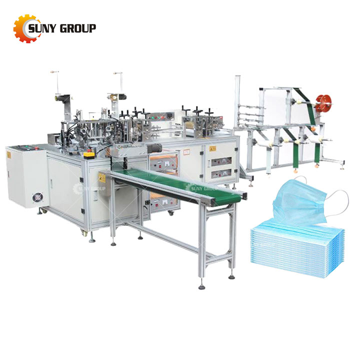
Summary of mask machine problems and detailed debugging process
Nowadays, mask machines all over the country are producing masks at full horsepower, but the machines are frequently used or problems are prone to occur during use. Today, the editor summarizes the problems that occurred during the production process of the mask machine, and also summarizes the debugging process of the mask machine. I hope you can see You can better understand the problem of the mask machine and solve the problem.
1. Loose wires when installing the bridge of the nose
2. The bridge of the nose is blocked
3. There are wrinkles in the bridge of the nose
4. The mask cloth feeding door frame is uneven
5. The mask cloth is pressed and wrinkled
6. The deformation of the mask is caused by the pressing wheel passing after the mask is pressed.
7. The mask cannot be completely cut off
8. The final pressure wheel of the adjustment machine is not smooth
9. The earband machine does not feed normally, and the width of the feed rail is adjusted
10. Abnormal feed of earband machine-sensor adjustment
11. Earring thread problem-push claws are not in place
12. The remote position of the earphone chain is adjusted.
13. Adjust the track width and position of the ultrasonic rigid mold
14. Head position adjustment
15. Adjustment of ear wire welding quality
16. Adjustment of the zero position of the ear frame rotation
17. Use ear threads to clamp and adjust the opening position of the claw ejector rod
18. Adjust the position of ear clippers
19. GB/T1459.19 Earband machine abnormal feed trajectory, adjustment of the width of the feed trajectory
20. GB/T1459.20-1988 ear-belt machine feed is abnormal, and the track feed inductor is adjusted
21. Earring thread problem-push claws are not in place
22. Earrings hanging wire problem-insufficient welding time
23. Ear strap hanging line problem-ear thread clamping position is high
24. The ear cord is not cut off-the ear cord is not on the turntable.
25. The ear cord is often cut-the ear cord is not caught in the claw
26. The ear thread scissors are constantly adjusted-the blade of the scissors is adjusted
27. The ear straps are poorly welded-the cylinder pressure is not enough
28. Wearing cloth is not smooth
29. Modular wave wheel adjustment
30. Installation and adjustment of mask folding mechanism
31. Adjust the transmission and cutting mechanism of the nose bridge
32. Mask width adjustment
33. Adjustment of the main embossing shearing wheel
34. Cheap adjustment of the host center
36. Adhesive masks appear after the welding rollers.
Mask machine debugging process
1. Select the power supply and vibrating source with the same number. The number of power supplies is usually marked near the vibrator interface. 2. Turn on the power and press the sound wave detection button to check whether the ammeter and voltmeter are deflected.
3. Turn off the power, insert the vibrator, and then turn on the power again. Press the sound wave detection button and observe the reading of the ammeter and voltmeter.
4. Open the small square on the right, press the screw, loosen the nut, fine-tune the screw, press the sound wave detection button every half circle, observe the ammeter reading, until the current reading is adjusted to 0.9A (no-load current is about 0.5A, die current About 0.9A), the maximum does not exceed 1a. At this time, observe the reading of the voltmeter, generally within 2V, if possible, use a multimeter with frequency detection to detect the frequency of the vibrator, generally below 19.9khz, generally not more than 20.05 khz
5. After satisfying the above conditions, hold down the screw, lock the screw in this position, tighten the nut, and remember not to let the screw follow during the process of tightening the nut. At this time, a test can be carried out to test the welding effect (under normal circumstances, it can be used normally after this step)
6. If the welding effect is not good, repeat the above 3.4.5
7. Connect the trigger line, that is, the socket at the lower end of the vibrator interface, which should be connected to the relay of the programmable logic controller.
Recommend products


CONTACT US:
If you have any requirement or suggestion, please fill in the form and send to us, thanks!E-mail:sunymachine@gmail.com | Whatsapp:+8613674945231