
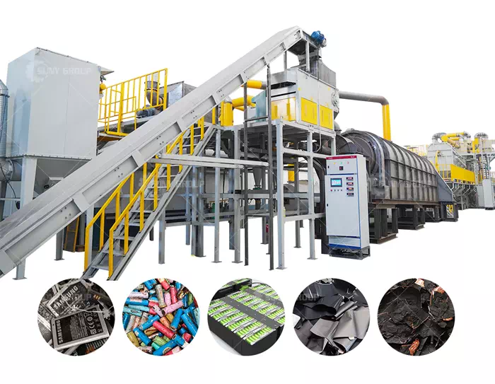
How to deal with waste lithium batteries, waste battery treatment process
A battery is a device for energy conversion and storage. There are many types of lithium batteries, and they are mass-produced and used in the current society. Lithium batteries have created a lot of convenience for mankind, and lithium batteries are needed in many places. In the steel shell lithium battery, the outer shell is a steel shell, the positive plate is aluminum foil, the negative plate is copper foil, the positive electrode material is lithium cobalt oxide, the negative electrode material is graphite, the separator is a polymer film, and the electrolyte is ethylene carbonate with lithium hexafluorophosphate dissolved in it. .
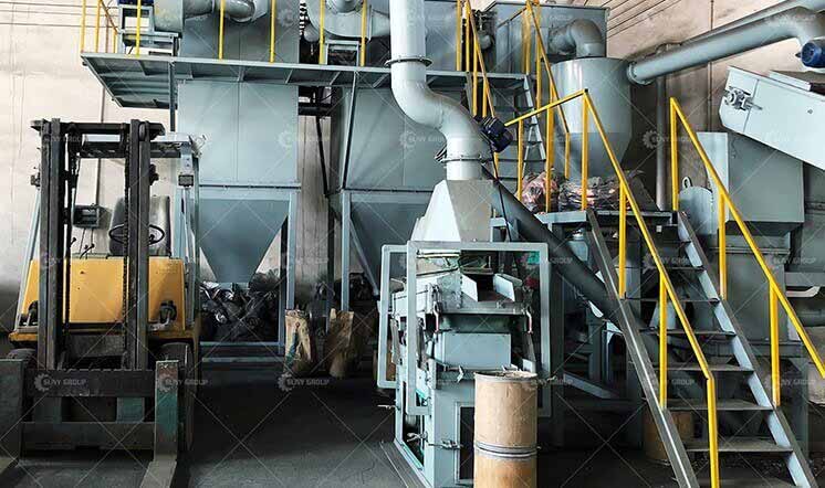
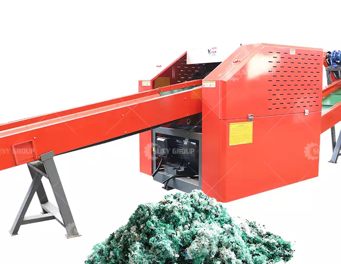
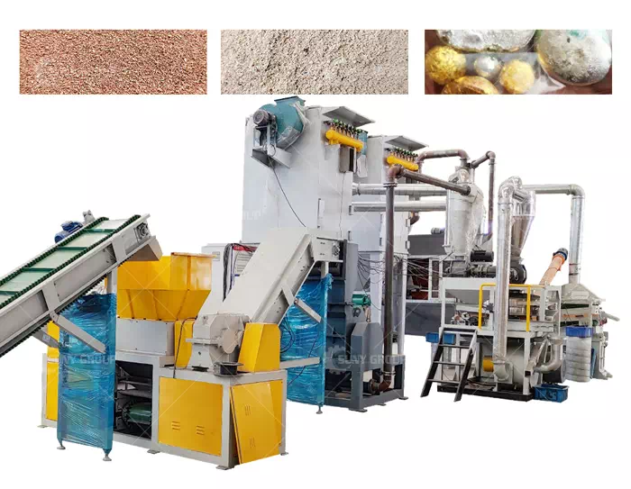
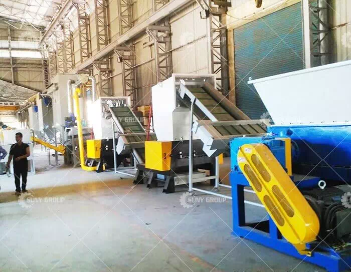
From the perspective of environmental protection and sustainable development, when lithium batteries cannot be used, they need to be recycled to reduce environmental pollution. Lithium battery processing and recycling equipment and crushing devices can well crush waste lithium batteries. The mixed granular materials such as lithium cobalt oxide powder and graphite powder can be filtered out from the discharge port at the bottom. The bulk lithium battery material flows to the sorting device, and the steel shell can be adsorbed on the conveyor belt. The state is sent to the material pool I, which greatly improves work efficiency, saves costs, and has a high utilization rate. The waste lithium batteries are processed, sorted, environmentally friendly, and rationally recycled.
Lithium battery recycling and processing equipment, including a crushing box, the top of the crushing box is fixedly installed with a feed hopper, the bottom of the crushing box is fixedly installed with support legs, and the bottom of the crushing box is fixedly installed with a discharge tube. A conveying channel is fixedly installed on the right side, and two conveying rollers are fixedly installed inside the conveying channel. The diameter of the middle of the conveying roller is larger than the diameter of its two ends, and a conveyor belt is arranged between the two conveying rollers. On the surface of the conveyor belt, evenly distributed leakage holes are opened on the surface of the conveyor belt, the conveying roller on the right side extends out of the conveying channel, and the bottom of the conveying channel is fixedly installed with a collecting box communicating with it.
The left and right sides of the crushing box and the lower left corner of the front of the conveying channel are fixedly installed with a drive motor. The output shaft of the drive motor on the crushing box is fixedly installed with a crushing shaft, and the crushing box is rotatably connected with the crushing shaft. On the inner wall of the other side, the two crushing rotating shafts are placed in parallel in the vertical direction, the bottom and top of the crushing rotating shaft on the top are fixedly installed with inclined blades, and both sides of the inclined blades are fixedly installed with auxiliary blades. , Both the bottom and the top of the crushing shaft at the bottom are fixedly installed with vertical crushing blades, and the driving motor on the conveying channel is fixedly connected with the mandrel of the conveying roller.
Inside the crushing box and located below the vertical crushing blades, a filter mesh layer inclined to the lower right is fixedly installed, and a discharge hopper is fixedly installed on the right side of the crushing box. The mesh layers are connected, and the right side of the discharge hopper extends above the conveyor belt surface. An intake fan is fixedly installed on the top of the material conveying channel, an air main pipe is fixedly installed on one side of the intake fan, and the air main pipe is fixedly installed on the top of the material conveying channel, and the bottom of the air main pipe An air delivery branch pipe is fixedly installed, the bottom of the air delivery branch pipe is fixedly installed with an air delivery nozzle, the air delivery nozzle at the front is inclined forward, and the air delivery nozzle at the rear is inclined backward.
A support frame is fixedly installed at the bottom of the collection box, a support plate is arranged inside the collection box, an isolation net layer is fixedly installed between the inner walls of both sides of the collection box, and the middle of the isolation net layer Located above the support plate, a sealing door is provided on one side of the collecting box. A collecting fan is fixedly installed inside the collecting box, a U-shaped air inlet pipe is fixedly installed on one side of the collecting fan, the air inlet pipe of the U-shaped air inlet pipe faces downward, and one side of the collecting fan A gas transmission pipe is fixedly installed, and the gas transmission pipe penetrates below the isolation net layer.
Compared with the prior art, the utility model has the advantage that the diameter of the middle part of the conveying roller is larger than the diameter of its two ends, which can make the middle of the conveyor belt surface higher, and convey to the main and branch pipes through the air inlet fan. The gas is ejected from the gas nozzle to achieve the effect of cleaning the impurities on the raw materials, and then the dust inside the conveying channel is transported to the bottom of the isolation net layer through the U-shaped air inlet pipe and the gas pipe through the collecting fan , To achieve the effect of filtering impurities, it can clean the impurities adhered to the raw materials, so that there are fewer impurities in the recovered raw materials.
Recommend products
CONTACT US:
If you have any requirement or suggestion, please fill in the form and send to us, thanks!E-mail:sunymachine@gmail.com | Whatsapp:+8613674945231